- Air Compressors
- Pneumatic actuators
- Gas springs
- Air treatment
- Pneumatic tools
- Electric tools
- Pomiar sprężonego powietrza
- Pneumatic connections
- Air hoses, reels
- Manometers and sensors
- Dehumidifiers
- Compressed Air Catalytic Converters
- Pneumatic installations
- Screw feeders
- Dampers and gate valves
- Pressure tanks
- Condensate separation
- Pneumatic lubricating oil
- Inert gas generators
- Medical kits
- Vacuum pumps
Complete Guide to Mechanical and Manual Pneumatic Valves: Types, Applications, and Selection
Table of Contents
Introduction to Mechanical and Manual Pneumatic Valves
Mechanical and manual pneumatic valves are fundamental components in industrial pneumatic systems, serving as control elements that direct, regulate, or block compressed air flow through direct physical action by an operator or through mechanical contact. Unlike solenoid valves, which require electrical signals to operate, these valves function through the application of mechanical force, making them particularly valuable in environments where simplicity, reliability, and independence from electrical systems are priorities.
In the context of American industrial automation, these valves represent a robust and versatile solution for numerous production processes, from automotive manufacturing to food processing, offering precise control with minimal intervention from complex electronic systems.
Operating Principles
The operation of mechanical and manual pneumatic valves is based on simple yet effective physical principles. When external force is applied through a foot pedal, lever, push button, or other mechanism, this action displaces internal elements such as pistons, discs, or balls that modify the compressed air pathways, allowing or blocking its circulation through different channels.
These valves are primarily classified according to their flow control function and their configuration of ports and positions:
- Ports: Indicate the number of valve connections (inlets and outlets). The most common configurations are 2, 3, 4, and 5 ports.
- Positions: Represent the distinct states the valve can adopt. We typically find valves with 2 or 3 positions.
The standard nomenclature to identify these valves uses two numbers separated by a slash, for example, "3/2" (3 ports, 2 positions) or "5/2" (5 ports, 2 positions). This classification is fundamental to understanding their specific application in a pneumatic circuit.
Key Points: Operating Principles
- Operate through direct application of physical force without requiring electricity.
- Classified according to the number of ports (connections) and positions (states).
- Standard nomenclature (X/Y) indicates ports/positions (e.g., 3/2, 5/2).
- Offer precise control of compressed air flow through internal moving elements.
Types of Mechanical and Manual Pneumatic Valves
The American industrial market offers a wide variety of mechanical and manual pneumatic valves, each designed to meet specific needs in different operating environments. Below, we analyze the main types available:
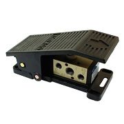
Foot Valves
Foot valves allow air flow control through pressure exerted by the operator's foot. This configuration frees the worker's hands for other tasks, which is especially useful in production operations where parts or tools need to be manipulated simultaneously.
Key features:
- Available in 3/2 and 5/2 configurations
- Ergonomic design to reduce operator fatigue
- Robust construction for demanding industrial environments
- Options with protection against accidental actuation
- Models with spring return or latching mechanism
Typical applications: pneumatic presses, welding machines, clamping operations, and workstations where the operator's hands need to be free.
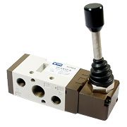
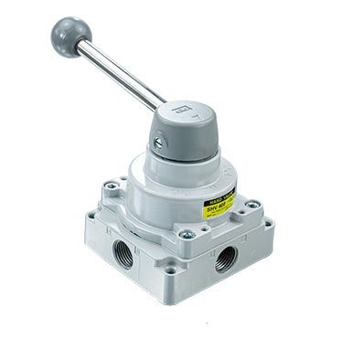
Lever Valves
Lever valves offer precise manual control through a lever movement that can be operated in different directions. They are highly versatile and allow intuitive control of air flow.
Key features:
- Available in 3/2, 5/2, and 5/3 configurations
- Options with automatic return or latching mechanism
- Designs with different actuation angles
- Versions with horizontal lever 4/3 for bidirectional control
- Construction in corrosion-resistant materials for aggressive environments
Typical applications: manual control of pneumatic cylinders, clamping systems, agricultural machinery, and material handling equipment.
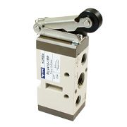
Roller Valves
Roller valves are activated through physical contact with a moving object, such as a piston or a moving machine part. They are essential for sequential automation and position detection.
Key features:
- Predominantly in 3/2 configuration
- Designed to detect mechanical positions
- Options with standard roller or with lever and roller
- Variants with one-way or bidirectional actuation
- Robust construction to withstand repetitive impacts
Typical applications: end-of-stroke detection in cylinders, sequence control in production lines, part positioning, and object presence detection.
Limit Switch Valves
Limit switch valves are a specialized type designed to detect the limit position of moving components. They act as mechanical sensors that convert physical movement into a pneumatic signal.
Key features:
- Typically in 3/2 configuration
- Various actuators: button, roller, lever with roller
- High precision in position detection
- Compact design for installation in confined spaces
- Versions with different actuation forces
Typical applications: stroke limits in automated systems, sequence control in machine tools, precise positioning, and safety systems.
Key Points: Types of Valves
- Foot valves free the operator's hands for other tasks.
- Lever valves offer precise and versatile manual control.
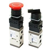
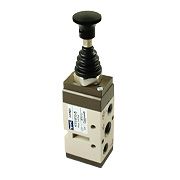
- Push button valves provide quick and direct activation.
- Roller valves detect mechanical positions in automated systems.
- Limit switch valves function as mechanical position sensors.
Industrial Applications
Mechanical and manual pneumatic valves find applications across various industrial sectors in the United States, where their simplicity, reliability, and ease of use make them indispensable components. Below, we detail some of the most relevant applications by sector:
Automotive Industry
- Control of pneumatic presses and assembly tools
- Clamping systems in assembly lines
- Verification stations and quality control
- Actuation of pneumatic cylinders in special machines
Food Industry
- Dosing control in packaging processes
- Compressed air cleaning systems
- Actuation of mechanisms in processing equipment
- Valves with food-grade certification
Machinery and Equipment Sector
- Motion control in machine tools
- Safety systems and emergency stops
- Part positioning in manufacturing processes
- Actuation of pneumatic tools
Packaging Industry
- Sequence control in packaging machines
- Product holding and handling systems
- Actuation of sealing and cutting mechanisms
- Foot valves for manual operations in packaging lines
Construction and Public Works
- Control of drilling equipment and pneumatic hammers
- Lifting and positioning systems
- Actuation of gates and locking mechanisms
- Robust valves for adverse environmental conditions
A practical example can be found in an American automotive assembly line, where foot valves allow operators to control the advancement of pneumatic cylinders that position components while keeping both hands free to guide the parts. This not only improves workstation ergonomics but also increases productivity and reduces cycle times.
Another common application in U.S. industry is the use of roller valves in packaging machines, where they detect the position of products on the line and sequentially activate different pneumatic actuators to perform operations such as folding, sealing, or cutting, all without the need for complex electronic sensors.
Selection Criteria
Choosing the right mechanical or manual pneumatic valve is crucial to ensure optimal system performance. Below, we present the main criteria that should be considered during the selection process:
Port and Position Configuration
Determine the necessary configuration according to the function the valve will perform:
- 3/2 Valves: Ideal for controlling single-acting actuators or for signaling functions.
- 5/2 Valves: Suitable for controlling double-acting cylinders where bidirectional control is required.
- 5/3 Valves: Necessary when a defined center position is required (closed center, open center, or pressure center).
Actuation Type
Select the actuation mechanism according to the desired interaction and operating environment:
- Foot: When the operator's hands need to be free.
- Lever: For precise manual control and operations requiring moderate force.
- Push Button: For frequent and quick activations.
- Roller: For position detection through physical contact.
- Mushroom Push Button: For emergency stop functions or when a large actuation surface is required.
Return Characteristics
Consider how the valve should behave after actuation:
- Spring Return: The valve automatically returns to its initial position when the actuation force ceases.
- Latching: The valve remains in the activated position until actuated in the opposite direction.
- Pressure Return: Uses air pressure to return to the initial position.
Technical Parameters
Evaluate the following technical parameters to ensure compatibility with your system:
- Working Pressure: Typically between 2 and 10 bar for standard valves.
- Nominal Flow Rate: Expressed in SCFM, must be sufficient for the application.
- Connection Size: From M5 to 1/2" NPT or larger, according to flow requirements.
- Operating Temperature: Typically between 14°F and 140°F for standard valves.
- Actuation Force: Important to ensure ergonomic and safe operation.
Environmental Considerations
Adapt the selection to the environment where the valve will operate:
- Corrosion Resistance:
- Corrosion Resistance: In humid or chemically aggressive environments.
- Dust Protection: In environments with suspended particles.
- Vibration Resistance: In machinery with oscillating movements.
- Special Certifications: ATEX for potentially explosive environments, FDA for food industry, etc.
Service Life and Maintenance
Consider aspects related to durability and maintenance:
- Expected Life Cycles: From 1 million to more than 50 million cycles depending on quality.
- Ease of Maintenance: Possibility of replacing internal components without dismantling the entire installation.
- Availability of Spare Parts: Important to reduce downtime.
Key Points: Valve Selection
- The port/position configuration must correspond to the type of actuator to be controlled.
- The actuation mechanism should be selected according to ergonomics and operating environment.
- Consider the necessary return behavior (automatic, latching, etc.).
- Verify that technical parameters (pressure, flow, connections) are compatible with your system.
- Evaluate environmental conditions and service life requirements for optimal selection.
Installation and Maintenance
Proper installation and adequate maintenance are fundamental to ensure optimal operation and extend the service life of mechanical and manual pneumatic valves. Below, we offer practical guidelines based on U.S. industrial experience:
Installation Recommendations
- Accessible Location: Install valves in easily accessible places for operation and maintenance.
- Proper Orientation: Follow manufacturer's guidelines regarding mounting position to avoid undue stress.
- Impact Protection: In aggressive industrial environments, consider installing additional guards.
- Leak-tight Connections: Use appropriate thread seals to prevent leaks at connections.
- Air Quality: Install the valve downstream of an adequate compressed air treatment system to extend its service life.
- Minimum Clearances: Respect minimum distances between components to facilitate handling and maintenance.
Preventive Maintenance Procedures
Establish a preventive maintenance routine that includes:
- Periodic Visual Inspection: Look for signs of wear, leaks, or damage to external components.
- Leak Verification: Use soapy water or ultrasonic detectors to identify incipient leaks.
- Functional Check: Regularly verify that actuation is smooth and that return functions correctly.
- External Cleaning: Remove accumulated dust and dirt that may affect the actuation mechanism.
- Lubrication: Apply compatible lubricant to external articulation points according to manufacturer's recommendations.
Corrective Maintenance
When problems are detected, follow these steps:
- Depressurization: Before any intervention, ensure the system is completely depressurized.
- Orderly Disassembly: Document the position of each component to facilitate subsequent reassembly.
- Internal Inspection: Examine gaskets, seals, and moving components for wear or damage.
- Component Cleaning: Use products compatible with the valve materials.
- Part Replacement: Replace damaged components using original spare parts.
- Functional Test: After assembly, verify correct operation before reintegrating the valve into the system.
Specific Recommendations by Valve Type
- Foot Valves: Regularly check the return spring resistance and the integrity of the protective cover.
- Lever Valves: Verify the tightness of fastening elements and the absence of excessive play in the mechanism.
- Push Button Valves: Examine the condition of the button and the smoothness of its movement.
- Roller Valves: Check that the roller rotates freely and that there are no deformations in the lever.
- Limit Switch Valves: Verify the accuracy of the switching point and adjust if necessary.
Proper maintenance not only extends the service life of the valves but also contributes to the energy efficiency of the pneumatic system by preventing leaks and ensuring optimal operation.
Troubleshooting Common Problems
Mechanical and manual pneumatic valves, despite their robustness, may present various problems during their life cycle. Below, we offer a practical guide to identify and resolve the most frequent issues in the U.S. industrial context:
Air Leaks
Symptoms: Audible hissing, pressure drop in the system, increased air consumption.
Possible causes:
- Worn or damaged gaskets or seals
- Poorly sealed threaded connections
- Cracked valve body
- Loose mounting screws
Solutions:
- Replace deteriorated seals and gaskets
- Apply appropriate pneumatic sealant to connections
- Replace the valve if it has structural cracks
- Check and tighten mounting screws
Actuation Difficulty
Symptoms: Excessive resistance when actuating the valve, irregular movement, or jamming.
Possible causes:
- Accumulation of dirt or debris
- Insufficient lubrication
- Wear of moving components
- Excessive working pressure
- Deformation due to impacts or overstress
Solutions:
- Clean the actuation mechanisms
- Lubricate according to manufacturer's specifications
- Replace worn components
- Verify and adjust system pressure
- Assess possible structural damage and replace if necessary
Return Failure
Symptoms: The valve does not return to its initial position after the actuation force ceases.
Possible causes:
- Weakened or broken return spring
- Obstruction in the internal mechanism
- Excessive component wear
- Insufficient pilot pressure (in valves with pneumatic return)
Solutions:
- Replace the return spring
- Disassemble, clean, and verify the internal mechanism
- Replace worn components
- Check and adjust pilot pressure
Incomplete Switching
Symptoms: The valve does not switch completely, resulting in reduced or irregular air flow.
Possible causes:
- Insufficient actuation force
- Wear of the internal mechanism
- Working pressure outside the recommended range
- Internal contamination
Solutions:
- Adjust the force or travel of the actuator
- Inspect and replace worn internal components
- Verify and adjust system pressure
- Clean the valve internally and improve air filtration
Slow Response
Symptoms: Excessive delay between actuation and effective valve switching.
Possible causes:
- Partial obstruction of internal passages
- Excessive lubricant viscosity (especially at low temperatures)
- Wear of moving components
- Insufficient working pressure
Solutions:
- Clean internal passages
- Use lubricant suitable for operating conditions
- Replace worn components
- Verify and adjust system pressure
Abnormal Noise
Symptoms: Unusual noises during operation such as clicking, hissing, or vibrations.
Possible causes:
- Loose or damaged internal components
- Internal leaks
- Excessive switching speed
- Vibrations transmitted from other components
Solutions:
- Inspect and secure all internal components
- Verify and replace deteriorated seals
- Install speed controllers if necessary
- Isolate the valve from vibration sources
Key Points: Troubleshooting
- Leaks are usually related to deteriorated seals or poorly sealed connections.
- Actuation difficulty generally results from contamination or lack of lubrication.
- Return failures typically involve problems with the spring or internal mechanism.
- Incomplete switching may indicate internal wear or inadequate pressure.
- For any persistent problem, consult with a specialist or contact the manufacturer.
Standards and Regulations
In the U.S. industrial context, mechanical and manual pneumatic valves are subject to various standards and regulations that ensure their safety, compatibility, and performance. Knowledge of these regulations is fundamental for both manufacturers and end users:
Applicable U.S. and International Standards
- OSHA Regulations: Establish safety requirements for industrial equipment, including pneumatic systems and components.
- ASME B31.3: Process Piping standard that may apply to pneumatic systems in certain industrial applications.
- NFPA 70: National Electrical Code, which may be relevant for installations where pneumatic and electrical systems interface.
Relevant ISO Standards
- ISO 4414:2010: Establishes general requirements for pneumatic systems and components.
- ISO 1219-1:2012: Defines graphic symbols for fluid power system diagrams, including pneumatic valves.
- ISO 5599-1:2001: Specifies mounting dimensions for 5-port pneumatic valves.
- ISO 5599-2:2001: Establishes interface requirements for 5-port pneumatic valves.
- ISO 15407-1:2000: Defines mounting dimensions for compact pneumatic valves.
Specific Standards for Special Applications
- ANSI/PMMI B155.1: For components used in packaging machinery.
- ISO 13849-1: For safety-related components in control systems.
- IEC 61508: For electrical/electronic/programmable electronic safety-related systems.
- FDA 21 CFR: For components used in food and pharmaceutical industries.
Certifications and Markings
Pneumatic valves marketed in the United States should have:
- UL Marking: Indicates compliance with Underwriters Laboratories safety standards.
- Declaration of Conformity: Document certifying compliance with relevant standards.
- Specific Markings: Such as explosion-proof ratings for hazardous environments or IP ratings for protection against particle and water ingress.
Considerations for Regulatory Compliance
When selecting pneumatic valves for your application, consider:
- Verifying that the manufacturer provides complete and up-to-date technical documentation.
- Checking that the valves have the required markings and certifications for your specific application.
- Ensuring compatibility with the standards of your particular industry.
- Maintaining compliance records for audits and inspections.
Compliance with these standards is not only a legal requirement but also ensures the safety, reliability, and compatibility of components in your pneumatic system, reducing operational risks and potential legal liabilities.
Conclusion
Mechanical and manual pneumatic valves represent fundamental components in modern industrial pneumatic systems, offering robust, reliable, and versatile solutions for compressed air flow control. Throughout this article, we have explored their operating principles, types, industrial applications, selection criteria, installation and maintenance recommendations, as well as strategies for troubleshooting common problems.
Proper selection of these components is crucial to ensure optimal performance and longevity of pneumatic systems. Factors such as port and position configuration, actuation type, return characteristics, and technical parameters must be carefully evaluated based on the specific requirements of each application.
At Pneumatig, we offer a wide range of high-quality mechanical and manual pneumatic valves, including foot valves, lever valves, push button valves, roller valves, and limit switch valves. Our catalog is designed to meet the needs of various industrial applications in the United States, providing components that comply with current standards and guarantee maximum reliability and performance.
We invite you to explore our product selection and contact our technical team for personalized advice on the selection and implementation of pneumatic valves in your system. At Pneuma
We invite you to explore our product selection and contact our technical team for personalized advice on the selection and implementation of pneumatic valves in your system. At Pneumatig, we are committed to providing quality pneumatic solutions that contribute to the success of your industrial operations.
Login and Registration Form