Table of Contents
Comprehensive Guide to Manual Pneumatic Valves: Types, Applications, and Selection
In the field of industrial automation and pneumatic systems, manual pneumatic valves represent fundamental components that enable direct and precise control of compressed air flow. Unlike solenoid valves that require electrical signals, these valves offer operation through human actuation, providing reliable, economical solutions that are especially useful in applications requiring direct operator intervention or in emergency situations.
This technical guide is designed for engineers, maintenance technicians, and purchasing managers in the U.S. industrial sector, offering detailed information on the different types of manual valves, their practical applications, selection criteria, and best practices for implementation in production environments.
What Are Manual Pneumatic Valves?
Manual pneumatic valves are mechanical devices designed to control the flow of compressed air in pneumatic systems through direct manual actuation. These components allow directing, blocking, regulating, or diverting air flow to pneumatic cylinders, actuators, and other circuit elements without requiring electrical power or automated control signals.
The primary function of a manual pneumatic valve is to provide the operator with direct control over the pneumatic system, enabling operations such as:
- Manual activation and deactivation of pneumatic actuators
- Emergency control when automated systems fail
- Equipment maintenance and testing operations
- Applications where human intervention is necessary for safety reasons
- Simple systems that don't justify investment in complete automation
Operating Principle
The operation of a manual pneumatic valve is based on the mechanical displacement of an internal element (spool, disc, or piston) that modifies the connections between the valve ports. This displacement is caused directly by the operator's physical action on the actuation mechanism (lever, button, selector, or pedal).
The typical operating process includes:
- Rest state: The valve maintains a predetermined position (normally closed or normally open) thanks to return elements such as internal springs.
- Actuation: The operator applies force to the actuation mechanism, overcoming spring resistance and displacing the internal element.
- State change: The internal movement modifies port connections, allowing air flow to actuators or blocking it according to configuration.
- Return: Upon releasing actuation (in spring-return valves), the spring returns the valve to its original position. In detented valves, the position is maintained until new actuation.
This mechanical principle guarantees operational reliability even in demanding industrial environments, without dependence on electrical supply, which is especially valuable in critical safety applications.
Types of Manual Pneumatic Valves
Manual pneumatic valves are classified primarily by their actuation mechanism, each designed for specific applications and ergonomics within the industrial environment.
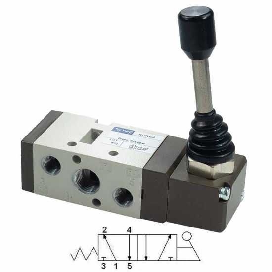
Lever Valves
Lever valves are probably the most common and versatile type of manual valve. Actuation is performed through a mechanical lever that can move in different directions depending on the design.
Main characteristics:
- Intuitive and ergonomic actuation
- Available in spring-return (monostable) and detented (bistable) configurations
- Short levers for tight spaces or long levers for greater leverage
- Options with lockable intermediate positions
Typical applications: Control of work tables, activation of pneumatic presses, operation of gripping fixtures, and systems where the operator needs to keep both hands free after actuation.
Push button valves offer actuation through direct pressure on a pushbutton. This design is ideal for applications requiring quick and repetitive actuations.
Main characteristics:
- Fast and precise actuation
- Reduced actuation force
- Compact and robust design
- Generally with automatic spring return
- Buttons of different sizes and colors for visual identification
Typical applications: Manual work stations, machine cycle activation, pneumatic emergency stops, and applications requiring momentary actuation.
Rotary Selector Valves
Rotary selector valves use a rotating knob to change between positions. This type is especially useful when multiple clearly differentiated control positions are needed.
Main characteristics:
- Clear selection between multiple positions (typically 2 or 3)
- Lockable positions through mechanical detent
- Visual indication of selected position
- Resistant to accidental actuation
Typical applications: Selection of operation modes (manual/automatic), switching between pneumatic circuits, and applications where position must be safely maintained for extended periods.
Foot pedal valves allow the operator to control the pneumatic system with their feet, leaving hands free for other tasks.
Main characteristics:
- Actuation through foot pressure
- Robust design to withstand operator weight and movement
- Non-slip base for operational safety
- Protection against impacts and contamination
Typical applications: Assembly operations where hands are occupied, press control, activation of clamping systems, and applications in footwear and textile industries.
Port and Position Configurations
Manual pneumatic valves are specified according to their number of ports (connection ports) and positions (possible operating states). This nomenclature is fundamental for selecting the appropriate valve according to pneumatic circuit requirements.
3/2 Valves (3 ports, 2 positions)
3/2 valves are most commonly used for simple control of single-acting actuators. They have three ports:
- Port 1 (P): Pressure supply connection
- Port 2 (A): Actuator connection
- Port 3 (R): Exhaust to atmosphere
In rest position, the outlet port can be connected to pressure (normally open - NO) or to exhaust (normally closed - NC). Upon actuation, the connection is reversed.
5/2 Valves (5 ports, 2 positions)
5/2 valves are essential for controlling double-acting cylinders. They have five ports:
- Port 1 (P): Pressure supply
- Ports 2 and 4 (A and B): Connections to the two cylinder chambers
- Ports 3 and 5 (R and S): Exhausts to atmosphere
When changing position, the valve reverses connections, allowing bidirectional actuator movement.
4/3 Valves (4 ports, 3 positions)
4/3 valves offer an additional center position, useful for stopping actuator movement at an intermediate position or maintaining pressure in both chambers. The center position can have different configurations:
- Closed center: All ports blocked (position retention)
- Exhaust center: Work ports connected to exhaust (pressure discharge)
- Pressure center: Work ports connected to pressure (force application in both directions)
Key Takeaways: Configuration Selection
- Use 3/2 valves for single-acting actuators and basic control applications
- Select 5/2 valves for double-acting cylinders with bidirectional movement
- Opt for 4/3 valves when intermediate stop position or precise control is needed
- Consider NC or NO configuration according to your application's safety requirements
Advantages of Manual Valves in Industrial Applications
Manual pneumatic valves offer multiple advantages that make them indispensable in numerous industrial applications, complementing or even replacing automated systems in specific contexts.
Operational Reliability
By not depending on electrical or electronic components, manual valves present exceptional reliability in adverse industrial environments. They are not affected by electromagnetic interference, voltage spikes, or electrical supply failures, guaranteeing continuous operation even in the most demanding conditions.
Maintenance Simplicity
The simple mechanical construction of these valves significantly reduces maintenance requirements. They don't require electronic calibration, programming, or diagnosis with specialized equipment. Maintenance interventions are generally limited to visual inspection, cleaning, and occasional lubrication—tasks that can be performed by technicians with basic pneumatics training.
Cost-Effectiveness
For applications that don't require complete automation, manual valves represent an economically advantageous solution. Initial cost is considerably lower than automated systems, and operating expenses are minimal as they don't consume electrical energy or require frequent specialized maintenance.
Direct Control and Safety
In critical safety applications, the capability for direct manual control is invaluable. Operators can intervene immediately in emergency situations without depending on control systems that could fail. This characteristic is especially important in industries such as food processing, pharmaceuticals, and chemicals, where safety protocols are strict.
Operational Flexibility
Manual valves allow quick adjustment of system operation according to changing production needs. In manufacturing lines with variable products or processes requiring frequent human intervention, this flexibility proves more practical than fully automated systems.
Energy Independence
In facilities where electrical supply is unstable or in classified hazardous locations where the presence of electrical equipment is restricted, manual valves operate without limitations, depending only on the supply of treated compressed air.
Selection Criteria: Practical Guide
Proper selection of a manual pneumatic valve requires analyzing various technical and operational factors to guarantee optimal performance, durability, and safety in the specific application.
Working Pressure
The valve's nominal pressure must exceed the system's maximum pressure with an adequate safety margin. Standard industrial valves typically operate between 0 and 145 psi (10 bar), although models exist for high-pressure applications up to 232 psi (16 bar) or higher.
Important considerations:
- Verify the minimum pilot pressure required for correct actuation
- Consider pressure variations in the system during the operating cycle
- Ensure that the pressure regulation system maintains values within the specified range
- For critical applications, select valves with verified pressure certifications
Flow Rate and Cv Coefficient
The nominal flow rate (expressed in SCFM at normalized pressure) determines the valve's capacity to supply sufficient air to the actuator. The Cv coefficient characterizes the valve's flow capacity.
Basic flow calculation required:
For a double-acting cylinder, the necessary flow is calculated considering chamber volume and desired stroke time. As a reference, a 2-inch diameter ISO cylinder with 4-inch stroke requires approximately 7 SCFM at 87 psi (6 bar) for fast cycles (< 1 second).
Actuation Type
Selection of the actuation mechanism should be based on operational ergonomics, frequency of use, and available space:
- Lever: Ideal for frequent operations with need for stable positions. Requires lateral space for lever movement.
- Push button: Perfect for quick and repetitive actuations in confined spaces. Generally with automatic return.
- Rotary selector: Excellent for clear selection between operating modes. Resistant to accidental actuation.
- Foot pedal: Essential when operator's hands must remain free. Requires floor space and additional safety considerations.
Construction Material
Body and internal component material should be selected according to the operating environment:
- Anodized aluminum: Industrial standard, excellent weight/strength ratio, suitable for most applications.
- Stainless steel: Necessary in food processing,pharmaceutical, and chemical industries. Superior corrosion resistance and facilitates cleaning according to hygienic regulations. Pneumatig offers options in stainless steel for demanding applications.
- Nickel-plated brass: Common in smaller valves, good corrosion resistance in dry environments.
- Technopolymers: For applications with reduced weight requirements or in the presence of intense magnetic fields.
Connections and Fittings
Connections must be compatible with the existing piping system. In the USA, the most common threads are:
- NPT thread (tapered): Standard in North America for pneumatic applications, seals through thread deformation.
- G thread (parallel ISO 228-1): Less common in the USA but found in imported equipment, requires sealing washer.
- Quick connections: Push-to-connect fittings for polyurethane or polyamide tubing, facilitate installation and maintenance.
Typical sizes range from 1/8" NPT for small valves to 1/2" NPT or larger for high-flow applications.
Ambient Temperature
Verify that the valve's operating temperature range is compatible with environmental conditions. Standard valves typically operate between 14°F and 140°F (-10°C to +60°C), but special versions exist for extreme temperatures (-40°F to 302°F / -40°C to +150°C) using special FKM or PTFE seals.
IP Protection and Environment
The IP (Ingress Protection) rating indicates resistance against dust and moisture:
- IP54: Basic protection, suitable for clean industrial environments.
- IP65: Complete protection against dust and water jets, recommended for most industrial applications.
- IP67: Resistance to temporary immersion, necessary in washdown industries or very humid environments.
Standards and Certifications
For applications in the United States, verify that valves comply with:
- ASME B31.3: Process piping code for pressure-containing components.
- OSHA regulations: Safety requirements for components integrated in machinery.
- NEC/NFPA 70: For valves with any electrical components in hazardous locations.
- FDA 21 CFR 177: Required in food processing and pharmaceutical industries.
- UL/CSA certification: Product safety standards recognized throughout North America.
Key Takeaways: Valve Selection
- Calculate required flow based on actuator volume and desired cycle time
- Select material according to environment: aluminum for general use, stainless steel for hygienic industries
- Verify connection compatibility with your existing pneumatic tubing system
- Ensure regulatory compliance according to your industrial sector and installation location
Applications in U.S. Industry
Manual pneumatic valves find application in practically all industrial sectors in the United States. Below are the most relevant uses in key industries of the U.S. manufacturing sector.
Food and Beverage Industry
The United States has a robust food processing sector representing a significant portion of manufacturing output. In this sector, manual valves perform critical functions:
- Packaging line control: Manual activation of filling, sealing, and labeling systems when operator intervention is required.
- CIP cleaning systems: Stainless steel manual valves to isolate sections during cleaning and sanitation procedures.
- Work tables: Control of pneumatic clamping systems in food preparation and handling processes.
- Emergency stops: Manual valves as backup for automated systems to guarantee food safety.
In these applications, valves must comply with strict hygienic regulations, use food-grade materials, and allow thorough cleaning.
Automotive Industry
The U.S. automotive sector, with significant presence of domestic and international manufacturers across the Midwest and Southern states, uses manual valves in:
- Manual assembly stations: Control of pneumatic tools such as screwdrivers, riveters, and presses.
- Clamping systems: Activation of jaws and fixturing devices in welding and assembly operations.
- Quality control: Actuation of testing and dimensional verification equipment.
- Line maintenance: Isolation valves for safe interventions in automated systems.
Packaging Industry
U.S. packaging and contract packaging companies employ manual valves for:
- Format adjustment: Quick configuration changes in packaging lines through rotary selectors.
- Feed control: Foot pedal valves to activate material feeding systems while operator handles product.
- Palletizing systems: Manual control of pneumatic grippers and lifting systems in semi-automated operations.
- Machine testing: Push button valves for test cycles and equipment adjustment.
General Manufacturing and Machine Shops
In diversified manufacturing, manual valves are essential for:
- Pneumatic presses: Two-hand control through button valves to guarantee operator safety.
- Machine tool clamping systems: Activation of chucks and fixtures through lever valves.
- Lift tables: Control of ascent/descent through 4/3 valves with center stop position.
- Welding equipment: Valves to control positioning and workpiece clamping systems.
Aerospace Manufacturing
In the precision-critical aerospace sector, particularly in manufacturing hubs like Washington State, Southern California, and the Southeast, manual valves are used in:
- Composite layup operations: Manual control of vacuum systems and compaction equipment.
- Assembly fixtures: Precise activation of positioning and clamping systems for aircraft components.
- Testing stations: Manual valves for controlled pressure application during component testing.
- Clean room applications: Stainless steel valves meeting stringent contamination control requirements.
Chemical and Pharmaceutical Industries
In sectors where safety and regulatory compliance are critical, manual valves provide:
- Emergency control: Manual shutdown systems independent of automation for critical situations.
- Hazardous locations: Certified manual valves for areas with explosion risk, eliminating electrical ignition sources.
- Dosing systems: Precise control through manual valves in processes requiring direct operator supervision.
- Equipment isolation: Shutoff valves for safe maintenance of reactors, mixers, and transfer systems.
Plastics and Injection Molding
In the extensive U.S. plastics manufacturing sector, manual valves control:
- Mold clamping: Manual activation of pneumatic clamps during setup and changeover.
- Part ejection systems: Operator-controlled ejection for quality inspection.
- Material handling: Vacuum gripper control for part transfer and packaging.
- Auxiliary equipment: Manual valves for granulator, dryer, and conveyor control.
Installation and Maintenance Best Practices
Proper installation and adequate maintenance are fundamental to guarantee optimal performance, durability, and safety of manual pneumatic valves in industrial applications.
Pneumatic System Preparation
Before installing any manual valve, it's essential to ensure the compressed air system is properly prepared:
- Air quality: Air must be filtered, regulated, and lubricated according to manufacturer specifications. A proper FRL unit is essential to eliminate particles, condensate, and provide necessary lubrication to moving components.
- Filtration: Minimum 40-micron filtration is recommended for standard valves, and 5-micron for precision or miniature valves.
- Dew point: Air should have a pressure dew point of at least -4°F (-20°C) to prevent internal condensation that can cause corrosion and malfunction.
- Oil content: For standard valves with lubrication, maintain 1-2 drops of pneumatic oil per cubic meter of air. For non-lubricated valves, air must be completely oil-free.
Installation Procedure
1. Positioning and Orientation
Mount the valve in a position that allows ergonomic actuation and maintenance access. Most valves can be mounted in any orientation, but verify manufacturer specifications. Avoid positions where condensate could accumulate in ports.
2. Pneumatic Connections
Use quality pneumatic fittings appropriate for the tubing type:
- For rigid polyamide or copper tubing, use compression or push-to-connect fittings according to diameter.
- For flexible polyurethane tubing, push-to-connect fittings facilitate quick and secure installation.
- Apply PTFE tape or liquid sealant on tapered threads (NPT), but not on parallel threads (G) which require a washer.
- Don't over-tighten fittings to avoid port deformation; use recommended torque.
3. Port Identification
Carefully verify port identification according to the pneumatic schematic:
- Port P (1): Connection to main pressure line from compressor
- Ports A and B (2 and 4): Connections to actuator chambers
- Ports R and S (3 and 5): Exhausts to atmosphere; install mufflers to reduce noise
4. Mechanical Fastening
Secure the valve firmly using:
- Mounting screws in threaded holes in the body
- Mounting brackets for installation on panels or supports
- DIN rails for mounting in cabinets or pneumatic panels
- Base plates when vibration isolation is required
Commissioning
Follow this procedure for initial startup:
- Visual inspection: Verify all connections are properly tightened and there's no visible damage.
- Gradual pressurization: Slowly open air supply, gradually increasing pressure to working value.
- Leak detection: With soapy water or leak detector, verify all connections and seals.
- Functional test: Actuate the valve several times verifying position change is smooth and complete.
- Actuator verification: Check that the pneumatic cylinder or actuator responds correctly in both directions.
- Regulator adjustment: If the valve incorporates flow regulators, adjust them to obtain desired actuation speed.
Preventive Maintenance Program
Adequate preventive maintenance significantly extends the service life of manual valves:
Monthly Inspection:
- Verify smooth operation of actuation mechanism
- Visually inspect leaks at connections and seals
- Check that mufflers are not obstructed
- Verify oil level in FRL unit lubricator
- Clean external dirt from valve body
Semi-Annual Maintenance:
- Drain and clean the air filter in the line
- Verify seal and gasket wear through pressure leak test
- Check that return mechanism functions correctly
- Inspect condition of fittings and connections
- Document any anomalies for trend analysis
Annual Maintenance:
- Disassembly and internal inspection (if technically possible and recommended by manufacturer)
- Preventive replacement of seals and wear components
- Deep cleaning of ports and internal passages
- Verification of torque values on critical connections
- Update maintenance log and service life record
Lubrication
Proper lubrication is critical for correct operation:
- Lubricated valves: Require continuous supply of pneumatic oil (ISO VG 32) through FRL unit lubricator. Once lubrication is started, it must not be interrupted.
- Non-lubricated valves: Use special self-lubricating seals and don't require oil. In fact, the presence of oil can damage these special components.
- Conversion: Generally it's not possible to convert a valve from one type to another without completely replacing internal components.
Key Takeaways: Effective Maintenance
- Ensure proper air treatment with correctly sized and maintained FRL unit
- Establish a regular inspection program based on usage frequency and operating environment
- Maintain documented record of interventions for predictive analysis
- Replace components before complete failure to avoid unplanned downtime
Common Errors and Troubleshooting
Knowing the most frequent problems and their solutions allows maintenance technicians to quickly resolve incidents and minimize downtime.
Valve Doesn't Change Position or Does So Incompletely
Possible causes:
- Insufficient pressure in supply line
- Internal obstruction from dirt or particles
- Swollen seals from incompatible oil or contaminants
- Excessive wear of actuation mechanism
- Return spring failure (in spring-return valves)
Solutions:
- Verify pressure at connection point with gauge; should be within specified range (typically 58-116 psi / 4-8 bar)
- Check condition of filters and replace if saturated
- Disassemble, clean with appropriate solvent, and verify seal condition
- Replace damaged seals using manufacturer's service kit
- In case of severe mechanical wear, consider complete valve replacement
Air Leaks at Ports or Connections
Possible causes:
- Threaded connections improperly tightened or without adequate sealant
- Damaged or aged O-rings
- Damage to body sealing surface
- Low-quality or incompatible fittings
- Overpressure exceeding specifications
Solutions:
- Re-tighten connections applying appropriate torque (not excessive)
- Apply proper thread sealant (PTFE for NPT, washer for G threads)
- Replace O-rings with original manufacturer replacements
- Verify system pressure doesn't exceed valve nominal rating
- Use quality certified fittings for pneumatic applications
Actuator Moves Slowly or With Little Force
Possible causes:
- Insufficient flow through valve (inadequate Cv)
- Flow regulators excessively closed
- Undersized tubing or with restrictions
- Working pressure lower than required
- Internal leaks in valve reducing effective flow
Solutions:
- Verify valve size (Cv) is adequate for required actuator volume and speed
- Adjust flow regulators to allow greater flow
- Replace pneumatic tubing with larger diameter if necessary
- Increase system pressure through pressure regulator adjustment
- Inspect valve internally and replace if significant internal leaks are present
Excessive Noise During Operation
Possible causes:
- Excessive actuator speed generating turbulence at exhausts
- Obstructed or missing mufflers on exhaust ports
- Vibrations transmitted through inadequate mounting
- Cavitation from excessive pressure or abrupt flow changes
- Internal wear generating abnormal turbulence
Solutions:
- Install or replace mufflers on all exhaust ports
- Reduce actuator speed through flow regulators
- Use anti-vibration mounting dampers
- Verify working pressure doesn't significantly exceed what's necessary
- Consider higher capacity or sintered-type mufflers for superior noise reduction
Actuation Mechanism Requires Excessive Force
Possible causes:
- Lack of lubrication on moving components
- Dirt or corrosion in actuation mechanism
- Misalignment of internal components
- Excessive pressure making state change difficult
- Wear or damage to mechanical components
Solutions:
- Apply appropriate lubricant to joints and external moving components
- Thoroughly clean mechanism removing accumulated dirt
- Verify correct alignment after disassembly and cleaning
- Reduce working pressure if possible without affecting performance
- Replace damaged components or consider complete replacement if wear is widespread
Valve Doesn't Return to Initial Position (Spring-Return)
Possible causes:
- Return spring failure or breakage
- Mechanical obstruction preventing movement
- Excessively swollen seals generating friction
- Residual pressure in return chamber
Solutions:
- Inspect and replace return spring if broken or weakened
- Disassemble, clean, and eliminate any internal obstruction
- Replace seals with original replacements of correct material
- Verify exhaust ports are not obstructed
- Ensure there's no back pressure in exhaust lines
Applicable Standards and Regulations
Compliance with standards and regulations is essential to guarantee safety, quality, and compatibility of pneumatic valves in industrial installations within the United States.
Primary U.S. Standards
OSHA Regulations
The Occupational Safety and Health Administration establishes essential health and safety requirements for industrial equipment. Pneumatic valves as safety components must:
- Be designed and manufactured to prevent hazards during their expected service life
- Include adequate instructions and safety warnings
- Comply with lockout/tagout (LOTO) requirements for maintenance
- Meet risk assessment standards per ANSI B11.0
ASME Standards
The American Society of Mechanical Engineers provides standards applicable to pressure equipment. Pneumatic valves must:
- Be designed according to sound engineering practices
- Use materials appropriate for service conditions
- Include clear specifications of maximum allowable pressure
- Undergo pressure testing according to applicable category
NEC/NFPA 70 (Hazardous Locations)
Fundamental for installations in potentially explosive atmospheres (chemical, petrochemical, food processing with combustible dust, pharmaceutical). Valves for these applications must:
- Be certified for corresponding hazardous location classification (Class I, II, or III; Division 1 or 2)
- Eliminate possible mechanical ignition sources
- Use non-sparking materials
- Include specific hazardous location marking with class and group
Relevant ISO Standards
ISO 5599 - Directional Control Valves
This standard defines:
- Mounting dimensions and interfaces for interchangeability
- Port designation and standard nomenclature
- Performance characteristics and test methods
- Graphic symbols for technical documentation
ISO 6358 - Flow Characteristics
Establishes methods to determine and express flow characteristics of pneumatic components:
- Definition of sonic conductance coefficient (C)
- Critical pressure ratio (b)
- Standardized measurement procedures
- Allows objective comparison between products from different manufacturers
ISO 4414 - General Rules for Pneumatic Systems
Provides guidelines for safe design, installation, and maintenance of pneumatic systems:
- Compressed air quality requirements
- Component and material specifications
- Safe installation practices
- Preventive maintenance procedures
Sector-Specific Regulations
Food Processing Industry
- FDA 21 CFR 177: Materials in contact with food
- USDA regulations: Meat and poultry processing requirements
- 3-A Sanitary Standards: Hygienic standards for equipment
- GFSI certification: Global Food Safety Initiative compliance
Pharmaceutical Industry
- cGMP (Current Good Manufacturing Practice): FDA pharmaceutical manufacturing standards
- USP Class VI: Material biocompatibility
- GAMP 5: Validation of automated systems
- 21 CFR Part 11: Electronic records and signatures
Quality Certifications
Quality pneumatic valve manufacturers typically hold:
- ISO 9001: Quality management system
- ISO 14001: Environmental management
- ISO 45001: Occupational health and safety
- UL/CSA certification: Product safety recognized throughout North America
Pneumatig works exclusively with certified manufacturers that rigorously comply with these standards, guaranteeing our U.S. customers components conforming to all applicable legal and quality requirements.
Pneumatig: Your Trusted U.S. Supplier
Pneumatig positions itself as a specialized supplier of high-quality pneumatic components for the U.S. industrial market, offering a complete catalog of manual pneumatic valves that meet the most demanding quality standards and North American regulations.
Advantages of Choosing Pneumatig
Extensive Product Catalog
Our catalog includes a wide range of mechanical valves covering:
- Valves with all actuation types: lever, button, selector, pedal
- Configurations from 2/2 to 5/3 way
- Sizes from mini valves to high-flow industrial models
- Standard and special materials (stainless steel, hazardous location versions)
- Lubricated and non-lubricated options according to application requirements
Certified Quality
All our products come from internationally recognized manufacturers that comply with:
- ISO 9001 quality management certifications
- Compliance with applicable U.S. standards
- Hazardous location certifications for explosive atmosphere applications
- Specific regulations for food processing and pharmaceutical industries
Specialized Technical Support
Our technical team offers:
- Guidance in component selection according to specific application
- Flow calculation and system sizing
- Recommendations on optimal pneumatic circuit configuration
- Post-sale support for installation and commissioning
- Technical problem resolution and existing system optimization
Efficient Logistics Throughout the USA
We guarantee:
- Immediate availability of high-turnover references
- Fast delivery throughout the United States
- Efficient management of urgent orders
- Complete technical documentation in English
- Invoicing and commercial service adapted to the U.S. market
Complete Pneumatic Solutions
In addition to manual valves, Pneumatig offers all components necessary for complete pneumatic systems:
Commitment to Excellence
At Pneumatig we understand that each industrial application has unique requirements. Therefore, our approach is not limited to product sales, but we position ourselves as a technical partner for our customers, offering:
- Detailed analysis of specific needs for each project
- Recommendations based on practical experience in the U.S. industrial sector
- Optimized solutions in terms of performance and cost
- Post-sale follow-up to ensure customer satisfaction
- Continuous updates on new technologies and products
Our experience in the U.S. market allows us to understand the particularities of key sectors such as automotive, food processing, packaging, aerospace, and general manufacturing, offering solutions specifically adapted to each industry.
Frequently Asked Questions About Manual Pneumatic Valves
Frequently Asked Questions About Manual Pneumatic Valves
-
-
What is the difference between a spring-return and detented valve?
A spring-return valve automatically returns to its initial position through a spring when actuation is released, being ideal for momentary operations. A detented valve maintains the selected position without need for continuous force until actuated again, perfect for applications where the state must be maintained for extended periods without operator intervention.
-
Can I use a manual valve instead of a solenoid valve?
Yes, in applications where human intervention is acceptable or desired. Manual valves are ideal for operations requiring direct supervision, emergency systems, low-cycle applications, or where simplicity and cost reduction are sought. However, for complete automation with high cycle frequency, solenoid valves are more appropriate.
-
What working pressure is appropriate for manual pneumatic valves?
Most industrial valves operate optimally between 58 and 116 psi (4-8 bar). Minimum pressure is typically 29-44 psi (2-3 bar) to guarantee correct actuation, while typical maximum is 145 psi (10 bar) for standard models. Special high-pressure valves exist (up to 232 psi / 16 bar) when the application requires it. Always verify manufacturer specifications for your specific model.
-
Do manual pneumatic valves need regular maintenance?
Yes, although maintenance is minimal compared to electronic components. Monthly inspection of operation and leaks is recommended, semi-annual verification of general condition, and annual maintenance with possible seal replacement. The key is ensuring clean, dry, and adequately lubricated compressed air through a well-maintained FRL unit, which significantly reduces wear.
-
How do I select the correct valve size for my application?
Size is determined primarily by required flow, which depends on actuator volume and desired cycle speed. Calculate the cylinder chamber volume and multiply by required cycles per minute. Compare this value with the valve's nominal flow (Cv) at working pressure. For critical applications, consult with Pneumatig's technical team for precise sizing.
Conclusion
Manual pneumatic valves constitute essential components in modern industrial automation, offering reliable, economical, and versatile solutions for pneumatic system control in a wide variety of applications. Their independence from electrical power, operational simplicity, and exceptional durability make them indispensable elements both in completely manual installations and in automated systems requiring human intervention or emergency functions.
Proper selection of a manual valve requires considering multiple technical factors: port and position configuration according to actuator type, adequate flow capacity for required cycle speed, materials compatible with the operating environment, and compliance with regulations applicable to the specific industrial sector. Applications in the United States span from food processing and pharmaceutical industries, where hygienic requirements are critical, to sectors such as automotive, packaging, aerospace, and general manufacturing, where reliability and cost-effectiveness are priorities.
Successful implementation doesn't end with proper selection; correct installation following best practices, use of properly treated compressed air through appropriate FRL systems, and a well-structured preventive maintenance program are fundamental to maximizing service life and minimizing unplanned downtime.
At Pneumatig, we understand the critical importance of each component in your production systems. Therefore, we offer not only certified quality products from internationally recognized manufacturers, but also the specialized technical support necessary to guarantee that each selected manual valve is the optimal solution for your specific application. Our commitment goes beyond sales: we position ourselves as your technical partner, providing expert guidance, efficient logistics throughout the United States, and post-sale follow-up to ensure your complete satisfaction.
Whether you need valves for a new installation, replacement of existing components, or upgrade of obsolete systems, our team is prepared to offer customized solutions based on years of experience in the U.S. industrial market. Contact Pneumatig to discover how our manual pneumatic valves can improve the efficiency, reliability, and safety of your industrial operations.
Industrial pneumatics constantly evolves, but the fundamental principles of reliability, simplicity, and efficiency that characterize manual valves remain valid. In an increasingly complex industrial environment, these valves continue demonstrating their value as robust and dependable solutions that withstand the test of time and the most demanding operating conditions.
Login and Registration Form