Pneumatic distributor - separating bars
To work with compressed air, in addition to its source, it is necessary to use hoses and pneumatic connectors. There are various types of couplings, such as auto, claw, clamp for CU hoses, plastic pneumatic couplings, ball valves, pneumatic quick couplings as well as strips, clamps and threaded couplings and reducers.
Pneumatic connectors can be divided into standard, stainless and mini. Another group are screwed joints that do not have any sealing, and the wires are sealed with a nut by pressing. They are usually used where specific conditions prevail, such as higher temperature, high stresses or twisting of the cables.
They can also be divided into straight couplings, tees, pneumatic swivel couplings with bearing, slow and high speed, elbows, straight through air hose couplings, reducing plug-in, cross-pieces, plugs and plugs, as well as shut-off valves, regulators and valves with the possibility of venting. Pneumatic plug connectors can have both male and female threads. Their assembly is easy, and additionally they allow for multiple connection and safe disconnection from the wires. Each branch of industry or production line can select the appropriate connectors for its needs, thanks to which it is able to guarantee safety and no leakage, and thus - failure-free. One of the most popular are dividing strips.
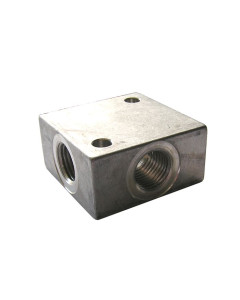
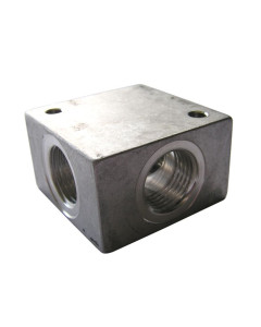
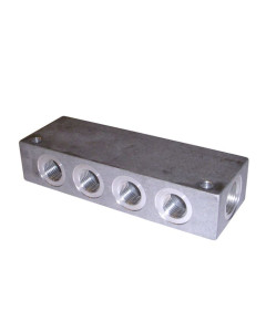
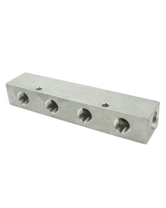
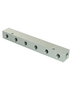
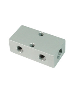
Pneumatic distributors, dividing bars are intended for connecting pneumatic devices, for example various pneumatic elements or pneumatic tools. They are used to limit the number of necessary fasteners and connection elements and to organize the lines in pneumatic systems.
Terminal blocks are used to divide the air supply into several routes, which enables the connection of several different devices. Thus, it is not necessary to supply the pneumatic system to the additional machine. This type of slats is also used in injection molds. They are usually made of aluminum or stainless steel.
Pneumatic distributors can be characterized by the number of working medium flow paths (two-way, three-way, four-way, five-way), the number of controlled positions of the flow control element (two-position, three-position), the method of control (electromagnetic, pneumatic, mechanical, mixed) and the method of delivering the working medium to the element control unit.
Pneumatic distributor - principle of operation
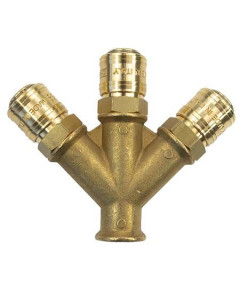
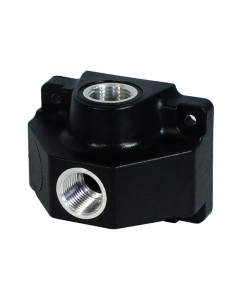
Pneumatic manifolds and manifolds, which are equipped with quick couplers, allow connection of air tools to the power source. They also allow for conveniently routing all pneumatic lines, thus reducing the number of consumer lines. They are used, among others, in the assembly of pipes, hoses and pneumatic lines, which are used to transfer working media in pneumatic systems. The collectors can also be used in the form of power plates for modular solenoid valves. Threaded distributors, on the other hand, allow the assembly of any elements with typical threads - inch G or metric M.
Both manifolds and threaded manifolds can be made of brass, nickel-plated brass, stainless steel, aluminum and plastic.
Pneumatic distributor - symbol
Pneumatic distributors, both in the technical drawings and in the construction documentation, are presented in the form of graphic symbols. They must be compliant with the PN-EN ISO 3952-1: 1998 standard and contain information on the number of paths, the number of valve positions, the method and type of control, and the designation of the flow paths. Manufacturers place all these data on the rating plates, together with graphic symbols for the purpose of their identification. Graphical symbols can be presented in full and simplified form. Both of them allow the identification of the spool valve, but the precise form allows in some cases to better define the functional properties of the spool valve.
Symbols for pneumatic distributors include information about the number of positions that the valve can reach and the number of flow path connection configurations, and information about the types of actuators. Above the symbol may additionally be placed the marking of the manual drive, which indicates an additional manual actuator. It is usually a button.
Pneumatic distributors can be divided according to the state of location:
- monostable - their initial state is the state in which the valve begins its entire work cycle. They return to it after the disappearance of the control signal;
- bistable - they hold their position after the disappearance of the control signal;
- normally closed (NC);
- normally open (NO).
The individual types of connections are marked as follows:
- power connections - 1 (P);
- working connections - 2, 4, 6 (A, B, C);
- venting connections - 3, 5 (R, S);
- control connections - 12, 14, 16 (X, Y, Z).
The 5/3 pneumatic distributor and the 5/2 pneumatic distributor are so-called five-way pneumatic valves. They are designed to control double acting pneumatic cylinders. The 3/2 pneumatic distributor (three-way pneumatic valve) is intended to control single-acting actuators. For valves with a 3/2 function, normally open (NO) or normally closed (NC) valves can be obtained. The pneumatic distributor ½, the so-called tee, is perfect especially in workshops when there are no additional pneumatic outputs.
The size of the valve is also important, i.e. the size of the connection threads located in the valve body, or sometimes in the connection plates and elements of the valve terminal. It is identified with the flow rate of the working medium through the distribution valve. In pneumatics, the most common pipe threads are from G1 / 8 "to G2", in the case of small-size valves, metric threads from M3 to M6 are also found. Unusual elements controlling the direction of the working medium flow require different threads.
Manual pneumatic distributor
Manual pneumatic distributors are the most popular among valves controlling the direction of compressed air flow. The most prominent among them are lever operated valves, which can be found in all machines and devices with pneumatic drive. They do not need pressure to swing, therefore they are able to work from 0 bar, or be used for vacuum. Depending on the method of controlling the pneumatic actuator, manual valves are used with spring return, i.e. monostable or with two stable positions, i.e. bistable valves. Manual bistable valves are usually equipped with a ratchet setting their position.
There are many combinations of types of manual pneumatic distributors control, so they can be installed in various types of machines and devices. A manual valve controlled by a lever, a manual valve controlled by a pull rod, a manual valve controlled by a button and a manual valve controlled by a plug can be distinguished. They can be used in so-called indirect control, where the pneumatic signal from the valve is fed to the actuation of the pneumatic valve. They are used in all types of pneumatic actuators (for example, piston rod, rodless, rotary and pendulum actuators), however, due to their variety (one-sided or two-sided), there are some rules for their selection. In the case of single-acting actuators, 3/2 or 3/3 valves are used. In the case of double-acting cylinders - 5/2, 4/3 and 5/3.
Manual pneumatic distributors with 5/3 or 4/3 function are used to stop the movement of the double-acting cylinder piston rod in any position. However, they come in different configurations of the so-called center position:
- in the middle position all cut-off roads;
- in the middle position receivers connected to the power supply;
- receivers deaerated in the middle position.

Login and Registration Form